How Does a Computer Boot?
Overview
Booting a computer is a low-level handoff across hardware, firmware, bootloader sectors, and kernel initialization routines.
This post elaborates on every phase of the boot sequence, answering the key questions surrounding hardware diagnostics, BIOS software interrupts, MBR sector limitations, memory address offsets, UEFI architecture, and Secure Boot key hierarchies.
Boot Process Architecture Flowchart
Here is the high-level architectural flowchart showing the entire end-to-end computer boot pipeline from power button press to kernel execution:
+---------------------------------------------------------------------------------------------------+
|                                COMPUTER BOOT SEQUENCE FLOWCHART                                   |
+---------------------------------------------------------------------------------------------------+
|                                                                                                   |
|  [Power Button Pressed]                                                                           |
|         |                                                                                         |
|         v                                                                                         |
|  [PSU Output Stabilizes] -> Sends "Power Good" Signal to Motherboard                              |
|         |                                                                                         |
|         v                                                                                         |
|  [CPU Reset State Released] -> Executes Reset Vector JMP F000:E05B                                |
|         |                                                                                         |
|         v                                                                                         |
|  [Northbridge Address Routing]                                                                    |
|         |                                                                                         |
|         +---> (Cold Boot) ---> Fetch Instructions from SPI Flash ROM                              |
|         |                                                                                         |
|         +---> (Warm Boot) ---> Fetch Cached Firmware Code from RAM                                |
|         |                                                                                         |
|         v                                                                                         |
|  [POST Diagnostics] -> Register Checks (0xAAAA / 0x5555), Timer, DMA, RAM Initialization             |
|         |                                                                                         |
|         +---> (Hardware Fail) ---> Output Hex Port 0x80 / Beep Codes                              |
|         |                                                                                         |
|         v                                                                                         |
|  [Keyboard IRQ 1 Check]                                                                           |
|         |                                                                                         |
|         +---> (Key Pressed: F12/DEL) ---> Jump to Firmware Setup Menu                             |
|         |                                                                                         |
|         +---> (No Key Pressed) ---> Execute INT 19h (Boot Loader Discovery)                       |
|                                                     |                                             |
|                                                     v                                             |
|                                     +-------------------------------+                             |
|                                     |    FIRMWARE SELECTION MODE    |                             |
|                                     +-------------------------------+                             |
|                                                     |                                             |
|                    +--------------------------------+--------------------------------+            |
|                    |                                                                 |            |
|                    v                                                                 v            |
|       [Legacy BIOS / MBR Mode]                                          [Modern UEFI / GPT Mode]  |
|                    |                                                                 |            |
|                    v                                                                 v            |
|       [Read Drive Sector 0 into 0x0000:0x7C00]                          [Read NVRAM efibootmgr]   |
|                    |                                                                 |            |
|                    v                                                                 v            |
|       [Verify MBR Boot Signature 0x55AA]                                [Mount FAT32 ESP Partition|
|                    |                                                                 |            |
|                    v                                                                 v            |
|       [Parse MBR 446B Code & 64B Partition Table]                       [Verify Secure Boot Sign] |
|                    |                                                    (PK -> KEK -> db vs dbx)  |
|                    v                                                                 |            |
|       [Load Active Partition VBR]                                                    v            |
|                    |                                                    [Execute .efi Binary]     |
|                    +--------------------------------+--------------------------------+            |
|                                                     |                                             |
|                                                     v                                             |
|                                      [OS Kernel Execution & Init]                                 |
+---------------------------------------------------------------------------------------------------+
1. Power On Self Test (POST) & Hardware Diagnostics
What is POST and what components does it verify?
The Power On Self Test (POST) is an immediate diagnostic process executed by motherboard firmware the moment power is supplied to a computer.
POST performs the following critical checks:
- Verifies CPU registers by writing and testing alternating bit patterns.
- Verifies the checksum integrity of the BIOS code itself.
- Tests foundational motherboard components including DMA (Direct Memory Access) controllers, programmable interval timers, and interrupt controllers.
- Initializes, sizes, and tests system main memory (RAM).
- Initializes primary BIOS data structures.
- Transfers control to specialized Option ROM extension BIOSes (such as graphics cards or storage controllers).
- Identifies, organizes, and selects available bootable storage devices.
What triggers POST and what is the Reset Vector?
The CPU begins executing POST the moment power reaches the processor (CPU power reset). When an x86 CPU powers on, it immediately executes instructions starting at its very first physical memory location, known as the Reset Vector:
JMP F000:E05B
This jump instruction points directly to physical SPI Flash ROM memory on the motherboard containing BIOS code.
How does the Northbridge handle Cold Boot vs. Warm Boot?
The Northbridge (or integrated memory controller) decodes physical addresses to either firmware ROM or system RAM depending on the boot state:
- Cold Boot: Triggered from a completely powered-off state. The Northbridge routes physical CPU memory fetches directly to non-volatile Flash ROM, forcing a full, comprehensive POST device discovery routine from scratch.
- Warm Boot: Triggered during a reboot while system RAM remains powered. The Northbridge points execution toward BIOS code already cached in RAM, skipping lengthy memory diagnostic routines for a faster startup.
- Quick Boot: A firmware option that bypasses extended hardware tests during POST.
How does POST verify hardware functionality via Assembly?
POST tests CPU registers by writing alternating bit patterns (0xAAAA and 0x5555) to verify that no register bits are stuck high or low:
MOV AX, 0xAAAA ; Binary: 1010101010101010
CMP AX, 0xAAAA
JNE HALT_ERROR ; Jump if register comparison fails

MOV AX, 0x5555 ; Binary: 055555 (101010101010101)
CMP AX, 0x5555 ; Compare alternate bit pattern
JNE HALT_ERROR
Low-level I/O controllers and system buses are tested using similar read/write verification patterns.
How are POST errors reported?
If a hardware failure occurs before video initialization, POST outputs raw hexadecimal error codes to I/O port 0x80 (read by diagnostic cards) and emits audible speaker beep codes.
What is the System Device Table?
During POST, the firmware builds a System Device Table (e.g. ACPI tables, SMBIOS, e820 memory maps) in memory detailing all connected hardware. The operating system kernel reads this table later to load appropriate device drivers.
2. The Legacy BIOS & 16-Bit Real Mode
What is the BIOS?
Basic Input Output System (BIOS) is low-level firmware flashed onto ROM or SPI Flash chips on the motherboard. It hosts POST routines and hardware initialization routines. Modern systems use SPI Flash memory, allowing firmware updates, though unpatched flash chips can be vulnerable to SPI rootkits.
What is Real Address Mode and its 1MiB memory limit?
BIOS runs in 16-bit Real Address Mode (Real Mode). In Real Mode:
- Paging and virtual memory are disabled. All addresses refer to raw physical memory.
- Addresses are calculated using a 20-bit address bus formula (
Segment * 16 + Offset), limiting total addressable memory to exactly 1 MiB.
Modern bootloaders (like GRUB2 or Windows Boot Manager) immediately switch the CPU into 32-bit Protected Mode or 64-bit Long Mode to bypass this 1 MiB limit.
How do 32-bit computations work when BIOS is stuck in 16-bit Real Mode?
When designing x86 processors in the early 1980s, 32 MiB addressable memory via combined segment registers was considered future-proof (since typical systems had under 10 MiB RAM). In 16-bit Real Mode, 32-bit calculations are executed by pairing two 16-bit registers together.
How do BIOS Software Interrupts work?
BIOS provides software interrupts (INT instructions) that function as hardware abstraction interfaces for bootloaders. A program reading from a disk does not need to know if the drive is ATA, SCSI, or SATA; it simply calls the BIOS interrupt handler.
Data passing mechanics in BIOS interrupts:
- Small Data: Passed directly in CPU registers (e.g.
AHfor function number,ALfor character or sector count). - Large Data: Stored in a RAM memory buffer, with a CPU register passing a pointer to the buffer.
Example assembly code writing a character using BIOS interrupt 0x10:
mov ah, 0x0E ; Function 0x0E: Teletype output
mov al, '!'  ; Character to display
int 0x10     ; Call BIOS video interrupt
How do operating system drivers replace BIOS interrupts?
Operating systems load dedicated kernel drivers to communicate directly with hardware controllers, bypassing slow 16-bit BIOS interrupts completely.
How does BIOS listen for keyboard presses during boot?
The moment power is applied, the BIOS initializes the keyboard controller (PS/2 or USB legacy controller). Every key press sends a raw electrical signal (scan code) over hardware interrupt request line IRQ 1.
IRQ 1 interrupts CPU execution and jumps to the BIOS interrupt handler. If the scan code matches keys like F12, F2, or DEL, the program counter jumps to the BIOS setup menu. This listener operates only during a brief timing window before BIOS calls INT 19h.
3. Master Boot Record (MBR) & Legacy Partitioning
MBR Sector & Bootstrap Flowchart
The following flowchart illustrates the sector parsing, memory loading, and VBR execution sequence during MBR booting:
+---------------------------------------------------------------------------------------------------+
|                                 MBR SECTOR & BOOTSTRAP FLOWCHART                                  |
+---------------------------------------------------------------------------------------------------+
|                                                                                                   |
|  [BIOS INT 19h Execution]                                                                         |
|         |                                                                                         |
|         v                                                                                         |
|  [Read Sector 0 (512 Bytes) from CMOS Boot Drive]                                                 |
|         |                                                                                         |
|         v                                                                                         |
|  [Load MBR Sector into Physical RAM Address 0x0000:0x7C00]                                        |
|         |                                                                                         |
|         v                                                                                         |
|  [Check Magic Boot Signature at Offset 0x1FE (Bytes 510-511)]                                     |
|         |                                                                                         |
|         +---> (Bytes != 0x55AA) ---> Non-Bootable Disk -> Check Next Boot Drive                    |
|         |                                                                                         |
|         +---> (Bytes == 0x55AA) ---> Valid MBR Found                                              |
|                                            |                                                      |
|                                            v                                                      |
|                             +------------------------------+                                      |
|                             |    MBR 512-BYTE STRUCTURE    |                                      |
|                             +------------------------------+                                      |
|                             |  1. Bootstrap Code (446 B)   |                                      |
|                             |  2. Partition Table (64 B)   |                                      |
|                             |  3. Boot Signature (2 B)     |                                      |
|                             +------------------------------+                                      |
|                                            |                                                      |
|                                            v                                                      |
|                             [Bootstrap Code Execution]                                            |
|                                            |                                                      |
|                                            v                                                      |
|                             [Scan 64-Byte Partition Table]                                        |
|                                            |                                                      |
|                                            v                                                      |
|                             [Locate Active Partition Entry]                                       |
|                                            |                                                      |
|                                            v                                                      |
|                             [Pass Disk ID (DL Register) to VBR]                                   |
|                                            |                                                      |
|                                            v                                                      |
|                             [Execute Volume Boot Record (VBR)]                                    |
|                                            |                                                      |
|                                            v                                                      |
|                             [Load OS Kernel / GRUB Stage 2]                                       |
+---------------------------------------------------------------------------------------------------+
What happens during Interrupt 19h?
After POST finishes, BIOS executes interrupt INT 19h to start the boot process. It attempts to locate a bootloader by checking devices in the configured CMOS boot order.
BIOS reads the first 512-byte sector (Sector 0) of a candidate drive into RAM at memory address 0x0000:0x7C00.
What is the Master Boot Record (MBR) structure?
The MBR is the first 512-byte sector of a partitionable storage device.
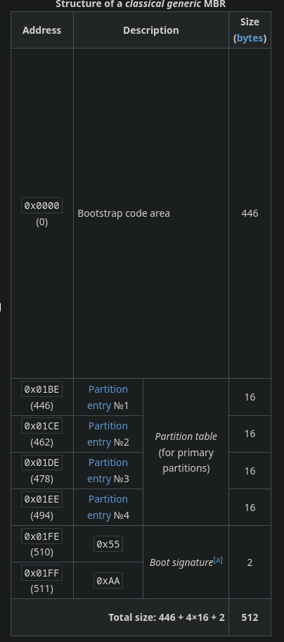
The 512-byte MBR sector consists of:
- Bootstrap Code Area (446 bytes): Code that initializes low-level registers and scans the partition table.
- Partition Table (64 bytes): Contains 4 primary partition entries (16 bytes each).
- Boot Signature (2 bytes): Must contain the magic bytes
0x55AAat the end of the sector.
Why is MBR limited to 2 TiB and 4 Primary Partitions?
MBR uses 32-bit Logical Block Addressing (LBA), capping maximum addressable sectors at 2^32. With standard 512-byte sector sizes:
Max Capacity = 2^32 * 512 bytes = 2,199,023,255,552 bytes (~2 TiB)
Because only 64 bytes are allocated for the partition table, MBR can hold a maximum of 4 primary partitions (16 bytes per entry).
Why can’t we shrink the 446-byte boot code area to add more partitions?
Shrinking the 446-byte boot code area to fit more partition entries is impossible because the 446/64/2 offset layout is a rigid, hardcoded industry standard. Changing these offsets would break compatibility with BIOS firmware, bootloaders, and operating system kernels worldwide.
What are MBR workarounds (ELP & 4096-byte Advanced Format)?
- Advanced Format (4Kn): Increasing sector size from 512 bytes to 4096 bytes increases maximum MBR capacity to 16 TiB, but breaks legacy bootloaders hardcoded for 512-byte sector math.
- Extended Logical Partition (ELP) & EBR: ELP acts as a container for additional partitions using a linked list of Extended Boot Records (EBR). Each EBR is a 512-byte sector with a 64-byte partition table pointing to the next logical drive.
- Dangerous 4 TiB Hack: Placing the final partition starting just under the 2 TiB boundary and stretching its size outward.
How does MBR bootstrapping work with the Volume Boot Record (VBR)?
The MBR code does not load the operating system directly. It scans the partition table for the active partition, loads that partition’s Volume Boot Record (VBR) into memory, and passes the boot drive identifier (from the CPU DL register) to the VBR. The VBR then loads the OS kernel.
What is Disk Identity and what are BootKits?
- Disk Identity: A 32-bit unique identifier embedded in the MBR used by operating systems like Windows to identify physical drives and automount drive letters (
C:\,D:\). - BootKits: Because MBR sectors lack cryptographic validation, malicious code or tools like Linux
ddcan overwrite the 446-byte boot code area with custom binaries or bootkit malware.
Where is boot order stored?
Boot order is stored in non-volatile CMOS SRAM powered by a CR2032 battery on the motherboard.
4. GUID Partition Table (GPT) & Modern Disk Layout
What is the GUID Partition Table (GPT)?
GPT is the modern disk partitioning standard introduced as part of the UEFI specification.
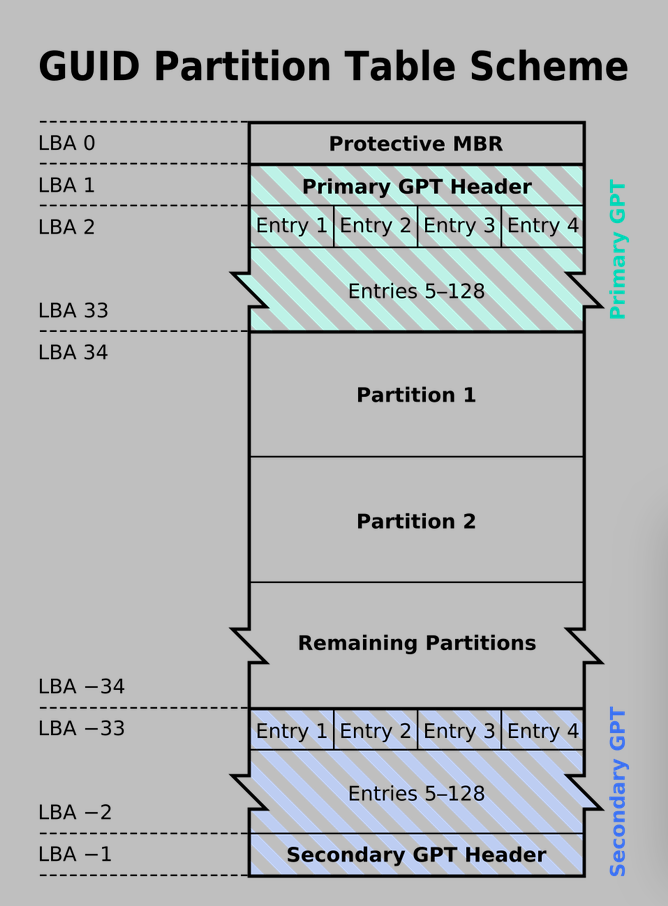
What are the advantages of GPT over MBR?
- 64-bit LBA Addressing: Supports drive capacities up to 8 ZiB (Zettabytes) with 512-byte sectors, or 64 ZiB with 4096-byte sectors.
- 128 Partitions: Supports 128 primary partitions natively without extended partition hacks.
- UUID Tracking: Every partition is tracked by a 128-bit Universally Unique Identifier (UUID). View GUIDs on Linux using
cat /etc/fstab. - Header Redundancy: Keeps a secondary backup copy of the GPT header and partition table at the very end of the physical disk.
What is the GPT LBA Layout?
- LBA 0 (Protective MBR): Contains a fake single MBR partition covering the entire drive. This prevents legacy MBR disk tools from seeing the disk as empty and overwriting GPT data.
- LBA 1 (Primary GPT Header): Holds partition array pointers, first/last usable blocks, disk GUID, and CRC32 checksums.
- LBA 2 to 33 (Partition Entry Array): Contains an array of partition entries defining GUIDs, start/end LBAs, and attribute flags.
5. Unified Extensible Firmware Interface (UEFI) & Secure Boot Pipeline
UEFI & Secure Boot Pipeline Flowchart
The following flowchart details how UEFI mounts the ESP partition, checks NVRAM paths, and executes the Secure Boot cryptographic signature check:
+---------------------------------------------------------------------------------------------------+
|                            UEFI & SECURE BOOT VERIFICATION PIPELINE                               |
+---------------------------------------------------------------------------------------------------+
|                                                                                                   |
|  [UEFI Firmware Power On]                                                                         |
|         |                                                                                         |
|         v                                                                                         |
|  [Initialize 32-bit / 64-bit CPU Execution Environment]                                           |
|         |                                                                                         |
|         v                                                                                         |
|  [Read Non-Volatile RAM (NVRAM) Boot Variables]                                                   |
|         |                                                                                         |
|         +---> (NVRAM Found) ------> Load Path (e.g. \EFI\archlinux\grubx64.efi)                   |
|         |                                                                                         |
|         +---> (NVRAM Wiped/USB) -> Fallback Path (\EFI\BOOT\BOOTX64.EFI)                          |
|                                           |                                                       |
|                                           v                                                       |
|                             [Mount FAT32 EFI System Partition (ESP)]                              |
|                                           |                                                       |
|                                           v                                                       |
|                             [Locate Target .efi PE32+ Binary]                                     |
|                                           |                                                       |
|                                           v                                                       |
|                             [Check Secure Boot Status]                                            |
|                                           |                                                       |
|                    +----------------------+----------------------+                                |
|                    |                                             |                                |
|                    v (Disabled)                                  v (Enabled)                      |
|          [Execute .efi Directly]                        [Verify Cryptographic Signature]          |
|                    |                                             |                                |
|                    |                         +-------------------+-------------------+            |
|                    |                         |                                       |            |
|                    |                         v (Hash in dbx)                         v (Valid db) |
|                    |                [Block Execution / Red Error]          [Execute .efi Binary]  |
|                    |                                                                 |            |
|                    +--------------------------------+--------------------------------+            |
|                                                     |                                             |
|                                                     v                                             |
|                                      [Pass Control to OS Bootloader]                              |
+---------------------------------------------------------------------------------------------------+
What is UEFI and how does it differ from BIOS?
UEFI (Unified Extensible Firmware Interface) is modern motherboard firmware that operates like a mini operating system in 32-bit or 64-bit mode, replacing legacy 16-bit BIOS.
Why is the EFI System Partition (ESP) formatted as FAT?
UEFI includes lightweight built-in file system drivers for FAT (FAT12, FAT16, FAT32) so it can navigate directories without needing heavy drivers for ext4, NTFS, or Btrfs.
The EFI System Partition (ESP) is a FAT32 partition holding executable bootloader files.
What is a .efi file?
A .efi file is a 32-bit or 64-bit PE32+ (Portable Executable) binary image containing UEFI applications or bootloaders.
Example path on Linux:
ls /boot/efi/EFI/archlinux
# Output: grubx64.efi
How does UEFI locate bootloaders via NVRAM?
UEFI does not scan physical active partition flags. Instead, it reads non-volatile RAM (NVRAM) variables (efibootmgr on Linux) containing direct file paths to bootloader .efi binaries:
BootCurrent: 0000
BootOrder: 0000,2001,2002
Boot0000* archlinux HD(1,GPT,39fdeb24...)/\EFI\archlinux\grubx64.efi
What is the Hardcoded Fallback Boot Path?
If NVRAM is cleared or a system boots from a removable USB drive, UEFI searches for a standardized hardcoded fallback path:
\EFI\BOOT\BOOTX64.EFI
6. Secure Boot Key Hierarchy
How does Secure Boot work?
Secure Boot verifies the digital signature of .efi bootloaders before execution to prevent rootkits and bootkits from running.
What is the Secure Boot Key Hierarchy?
- Platform Key (PK): The master key installed by the motherboard manufacturer. Proves physical administrative ownership over the firmware.
- Key Exchange Key (KEK): Signed by PK, used to authenticate updates to the signature database.
- Signature Database (
db): Allow-list containing public keys of authorized operating system bootloaders. - Forbidden Signature Database (
dbx): Blacklist containing signatures and hashes of compromised bootloaders blocked from executing.
Summary: BIOS vs. UEFI & MBR vs. GPT
| Feature | Legacy BIOS / MBR | Modern UEFI / GPT |
|---|---|---|
| Execution Mode | 16-bit Real Address Mode (1 MiB memory limit) | 32-bit or 64-bit Protected Mode |
| Max Capacity | 2 TiB limit (32-bit LBA) | 8 ZiB to 64 ZiB (64-bit LBA) |
| Partitions | 4 Primary Partitions (or ELP/EBR linked list) | 128+ Native Partitions |
| Boot Location | Raw Sector 0 (MBR loaded to 0x0000:0x7C00) |
FAT32 ESP executing .efi PE32+ binaries |
| Boot Order | CMOS SRAM (CR2032 battery) | NVRAM Variables (efibootmgr) |
| Boot Security | None (Vulnerable to MBR bootkits) | Cryptographic Secure Boot (PK, KEK, db, dbx) |
| Fallback Path | Reads sector 0 signature 0x55AA |
\EFI\BOOT\BOOTX64.EFI |
Discussion (0)
Leave a Comment